Posted on 26th Oct 2023

The industry wants to save energy in utility air screw compressors and is trying different ways to implement the same, says CM Industry Supply Automation - Servo Drive & Servo Motor Expert.
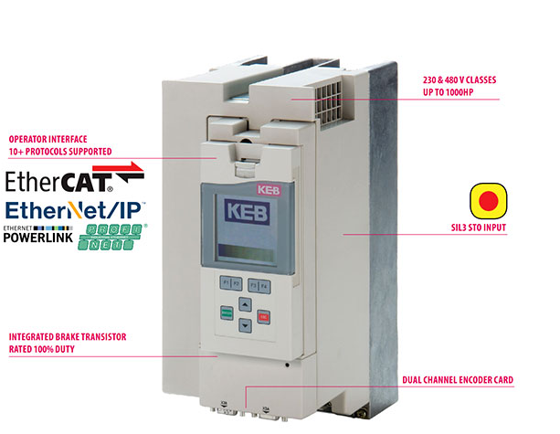
For the given demand for air volume, the industry has planned around two-thirds to be supplied by fixed load of compressors. The balance is to be supplied by the Variable Frequency Drive (VFD) such as KEB F5 Drive OR KEB F5 modulating air compressor.
The air screw compressor loses energy in generation in the compressor house, in the distribution at the compressed air header and branch piping, and in usage. This is in two ways that is machine usage and air leakage in the final pneumatic control elements inside the machine.
According to Ashok S., the industry is experimenting with several approaches to accomplish energy conservation in utility air screw compressors. About two thirds of the air volume required will be provided by fixed load compressors, according to industry plans. The modulating air compressor of the Variable Frequency Drive (VFD) will supply the balance.
Let's talk about the dynamics in header pressure changes, generating pressure, and compressed air flow that lead to the necessity for variable frequency drives (VFDs) in screw air compressors.
Since the compressor discharge pressure varies according to the process's air flow demand, a VFD is required for the compressor system. Since compressed air pressure is a dynamic variable, header pressure or compressor discharge pressure can be optimized and steadied by applying a variable frequency drive (VFD) such as KEB F5 to the compressor control.
1. Consider the case study of a 45 KW air compressor that runs nonstop. The compressor load-unload pressure band is maintained by the industry essentially between 6 and 8 Bar, or 0.5 Bar to 2 Bar. The compressor loads and unloads repeatedly throughout the day to accommodate process demand.
2. The industry is attempting to operate the compressor load-unload ratio at 80:20 economically and is monitoring the same in order to reduce the number of hours that the compressor is left running unloaded. Since unloaded power usage is 40% of rated compressor KW, it regularly modifies load-unload pressure settings to achieve maximum loading hours and minimize daily unload hours.
3. As a result, VFD such as KEB F5 Drive OR KEB F5 is adapted to save. This is accomplished by reducing the pressure band to a pin point, formerly set at 6.5 to 7.5 Bar, at around 6.5 Bar. Unloaded power is conserved by the VFD. As a result, the user saves compressor KW by lowering from 7.5 to 6.5 Bar at lowered pressure via VFD. Measured savings, however, are lower. According to BEE rules, every bar pressure drop from 7 to 6 Bar results in power savings of 6 to 10%.
1. Installing a separate air receiver close to the cleaning hose area is required to address this cleaning air application, which requires a significant amount of air withdrawal in bulk. The receiver should be sized for a single cleaning application and should not permit many users to clean simultaneously. Instead of the current 7 Bar of air pressure, the air receiver will only hold 4 Bar of air pressure. The air receiver will only be maintained at 4 Bar thanks to a large spring-loaded air line regulator that is mounted at the feed end of the receiver.
2. Create a spiral tubing roughly 10 feet long with quarter-inch copper tube at the 7 Bar air line usage point, and then provide an output for cleaning. At the outlet point, this will use only 40 CFM at about 3 Bar. Here, constant and low flow cleaning is carried out with a fixed and sustained pressure reduction that is also sized to the cleaning application without choking.
3. The following factors cause significant pressure dips and variations in compressed air header pressure:
a) An abrupt cessation of air flow during a vigorous cleaning operation
b) Regular use of the pneumatic cylinders installed in the machinery. When the electro valves on those pneumatic cylinders leak outside, these will use additional energy.
c) Despite the firmness of pipe fittings, hose joints, etc., air leakage flow causes a steady decline in pressure.
Therefore, if a VFD is retrofitted to a screw air compressor and it is operated at a partial loading of, say, two thirds of the compressor's rated KW, significant savings will be realized. VFDs must be operated to provide smooth input, slowly ramp up and down output, and a range that matches the KW of the compressor package in order to save energy.
In the end, a system can only save energy through VFD if its compressor, compressed air, and compressed air treatment parameters—which include dryers and filters—are in good condition. You risk energy loss in the compressor house and internal installations, in the distribution piping system, and at use locations when the laminar and streamlined energy flow via consistent air pressure is suddenly hindered inside without your knowledge.
The majority of purchasers choose the most efficient compressor, subsystems, and overall package over the industry standard for compressor operation. However, they forget to make sure that best installation methods are followed after spending a nice bundle on the compressor. A faulty installation might cause a good compressor system to function poorly for the rest of its life. From the day of installation, inefficiency grows, leading to a decrease in CFM production per operating KW and an increase in failures. Therefore, it's critical to eliminate system flaws using predictive and monitoring techniques. If a compressor and compressed air system is unhealthy, adding a VFD such as KEB F5 Drive OR KEB F5 by CM Industry Supply Automation will make it even worse and reduce the anticipated energy savings.