

Posted on 23rd Sep 2026
Variable Frequency Drives (VFDs) have become an essential part of modern industrial automation. They provide precise motor-speed control, process flexibility and energy-efficient operation across pumps, fans, compressors, conveyors, machine tools and production equipment. However, a plant with a large number of electrically controlled motor loads may also require careful management of its overall power quality and reactive power demand.
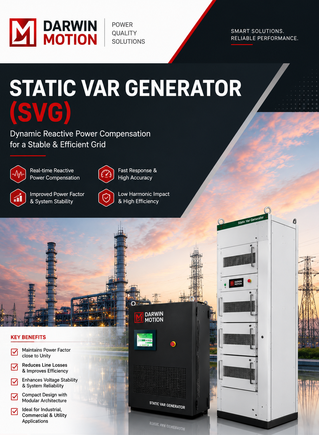
This is where SVG for VFD Applications can provide a dynamic approach to reactive power compensation. A Static Var Generator (SVG) continuously monitors the electrical system and responds to changing reactive power requirements using power-electronic technology. Darwin Motion, a Darwin Motion AC Drive manufacturer, offers SVG solutions intended for industrial systems where VFDs and other dynamic loads operate together.
VFDs electronically regulate the frequency and voltage supplied to motors. In a modern plant, several drives may start, stop or change operating levels throughout the production cycle. Alongside VFDs, the same electrical network may supply transformers, induction motors, compressors, pumps, HVAC equipment and other inductive loads.
The combined operation of these loads can result in changing reactive power requirements. Instead of treating power factor correction as a fixed requirement, an industrial facility may benefit from a compensation system capable of adapting to actual operating conditions.
Production machinery rarely operates at a constant load throughout the day. A motor may run at different speeds, production lines may be started sequentially, and auxiliary equipment may switch according to process requirements. These variations can cause the reactive power profile of the electrical installation to change continuously.
Excessive reactive current can increase the loading of transformers, cables and switchgear. Managing reactive power can therefore form an important part of an overall electrical-efficiency strategy, particularly in facilities with multiple motor-driven loads.
A Static Var Generator works as a power-electronic compensation system connected to the electrical network. It monitors electrical parameters and determines the reactive current required by the installation. The SVG can then inject or absorb reactive current according to the instantaneous requirement.
Darwin Motion states that its SVG uses high-speed IGBT technology and intelligent DSP control for dynamic compensation, with a published response time of approximately 5 milliseconds.
Conventional capacitor-based correction generally operates through switching stages. An SVG, by contrast, provides continuous and stepless compensation. This characteristic can be useful in VFD-based facilities where electrical demand changes frequently.
When the operating condition of a VFD-driven system changes, the reactive power requirement can also change. A fast electronic compensation system can react to these variations without depending on multiple mechanical capacitor-switching stages.
It is important to understand that an SVG and a VFD perform different functions. A VFD primarily controls the speed, torque and operating characteristics of an electric motor. An SVG operates at the electrical-system level to manage reactive power and support power quality.
In a VFD-intensive plant, these technologies can therefore serve complementary purposes. The VFD manages the motor-driven process, while the SVG addresses reactive power requirements of the electrical installation.
| VFD | SVG |
|---|---|
| Controls motor speed and torque | Manages reactive power |
| Optimizes motor operation for the process | Supports electrical power factor management |
| Installed as part of motor-control architecture | Connected to the electrical distribution system |
| Responds to process-control requirements | Responds to reactive-power requirements |
SVG technology can be evaluated in facilities where VFDs form a significant portion of the electrical load. The appropriate solution depends on the actual load profile, system voltage, reactive-power demand and installation architecture.
Selection of an SVG should be based on actual electrical measurements rather than simply the total installed VFD capacity. Darwin Motion's published specifications include system voltage ranges from 208V to 690V AC, compensation capacities from 30A to 600A, and RS485 Modbus RTU communication, with Ethernet available as an option.
VFD-driven processes may operate at different speeds throughout the production cycle. Continuous compensation allows the reactive-power controller to adapt to the changing requirement of the electrical system.
Modern industrial electrical systems can experience both inductive and capacitive operating conditions. Darwin Motion's SVG specifications include capacitive as well as inductive compensation capabilities.
Industrial automation environments increasingly require equipment to communicate with supervisory systems. Depending on the configuration, Darwin Motion SVG systems provide RS485 Modbus RTU communication and optional Ethernet connectivity for monitoring and integration.
Automatic Power Factor Correction (APFC) systems based on capacitor banks can be useful for relatively predictable reactive loads. However, VFD-intensive installations may have changing electrical requirements that call for a more responsive compensation method.
The appropriate technology should be determined from measurements and the characteristics of the electrical installation rather than from the presence of VFDs alone.
Measure active power, reactive power, power factor, current and voltage under different operating conditions. Measurements should cover minimum, normal and peak production states.
The SVG capacity should be selected according to the actual reactive-power requirement and the desired operating power factor. Simply adding together the ratings of all VFDs may not provide an accurate sizing basis.
Determine whether compensation is required at the main incomer, a specific distribution board or near a group of VFD-driven loads. The installation point should be selected after reviewing the plant's electrical architecture.
If additional drives, motors or production lines are planned, the compensation system should be evaluated with the future load profile in mind. A modular SVG arrangement can provide additional flexibility for expansion.
Darwin Motion AC Drive manufacturer provides industrial technologies covering motor control and power-quality applications. Its SVG solution is designed around dynamic reactive power compensation for industrial and commercial electrical systems.
For VFD-based facilities, combining appropriate motor-control technology with a properly engineered power-quality strategy can help create a more stable and efficient electrical environment. Darwin Motion's published SVG portfolio also identifies applications across manufacturing, automotive, steel, cement, textile, water treatment, HVAC, renewable energy and other sectors.
VFDs provide precise and efficient control of industrial motors, but the complete electrical system must also be evaluated for reactive power and power-quality requirements. An SVG can complement VFD installations by dynamically compensating reactive power, supporting power-factor management and responding to changing electrical conditions.
For facilities with multiple VFD-driven loads, variable production requirements or rapidly changing reactive demand, a properly sized Static Var Generator can be considered as part of the plant's broader power-quality strategy. Darwin Motion combines its experience as an AC Drive manufacturer with Static Var Generator technology to address these industrial electrical requirements.
SVG for VFD Applications refers to using a Static Var Generator in an electrical system containing Variable Frequency Drives to dynamically compensate reactive power and support power-factor and voltage performance.
Yes. An SVG can be applied at an appropriate electrical distribution point serving multiple VFD-driven loads. The required capacity should be determined from the measured reactive-power profile of the installation.
No. A VFD controls motor speed and torque, whereas an SVG manages reactive power at the electrical-system level. They perform different functions and can be used together.
SVG technology is designed for dynamic reactive power compensation and can help improve the operating power factor when correctly sized and installed according to the site's electrical conditions.
Darwin Motion combines AC Drive technology with power-quality solutions such as Static Var Generators, allowing industrial users to address motor-control and reactive-power requirements within a broader electrical-system strategy.